Note that this step is assuming you're using the professional PCB that you purchased from my store. If you want to make your own PCB at home, I have the files @GitHub for a single-sided home-made board available if you want to make your own board. And a separate tutorial for soldering on it.
There are lots of great tutorials on basic soldering, so if you've never soldered, go check some out, then come back here. Here are a few:
Collin's Lab: Soldering - By Collin's Lab / Adafruit Industries
How to Solder Correctly - and Why (Curious Inventor)
Soldering Basics (Sparkfun)
Ready? Ok, here we go...
Let's start with power. Place the power jack (J2) through the holes of the lower left of the PCB:


After pushing the jack onto the board, it should stay nicely until you're ready to solder.
Next is our first electrolytic capacitor (C1). Note that the white stripe (on the capacitor) is facing the nearest edge of the board - this is important as it is polarized. Once it's resting on the board, you should separate the legs away from each other. This will help the capacitor stay put while you flip it over to solder them:


Let's go ahead and solder the power jack and the capacitor leads now:

Then snip the leads of the capacitor:

After cutting the 2 leads, it should look something like this:

Now for the voltage regulator (IC2) and the 2nd electrolytic capacitor (C2):
Note how the voltage regulator is put in - do not reverse it! It should stay in just fine when you flip the board upside down to solder. The capacitor on the other hand will not, unless you bend the leads away from each other like the first one we just did. This capacitor goes in opposite of how the 1st one went in - the white strip should face toward the inside of the board. Once you have the voltage regulator and capacitor in properly, go ahead and flip the board over:

Solder, then clip the leads:

Grab your 220 Ohm resistor (R1), and bend the leads so that it's shaped like below:

Place the resistor onto the board where it says 'R1' (Note: it does not matter how you place the resistor in - it's not polarized so there is no - and +), spread the leads away from each other. Then place the red LED next to it. Make sure that the flat edge of the LED lines up with the flat edge on the board because the LED has polarity. Then spread apart the leads on the LED also:


Solder, then clip the leads:

Good job so far! As of now, your board should look like this:

Let's give it some power - plug it in with your 9V DC power supply, and if all is well, your LED will turn on. If you smell anything burning, or see smoke, immediately unplug it!

Let's check the voltage too. Get out your multimeter, and set it to test 5V. I have a Sparkfun one, so I put my dial on '20V'. Now flip your board upside down and touch your red probe to the top joint of the voltage regulator, and the black lead to the middle one. Your meter should read very close to 5.00 volts:

If you wish to take a break, this is a good place to do so. You've earned it after all.
Ok, let's carry on...
Let's install the male breakaway headers (collectively 'J1'). If you ordered the kit from me, they're ready to go. If you ordered them yourself from a place like Sparkfun, you're going to have to 'break away' 2 lengths of 3 pins. Go ahead and put both in into J1 (the tall side facing up), then place some Scotch tape over them to help keep them in place:

Then flip the board upside down and solder (no need to snip/clip):

Flip back around, and remove the tape - they'll stay on their own now:

Let's do the IC socket now. Snap the socket into place, taking note of the notch at the end. If you hold the board as shown below, the notch should be at the right-hand side...make sure you place it in this way because if you get it backwards, it will be a pain to remove later. There's no need to tape this part down (or bend the leads - they're not even long enough anyway) as it should snap right in nice and snugly:

Then solder every pin:

Let's put in the crystal (Y1) and the 2 ceramic disc capacitors (C3, C4). None of the 3 parts are polarized, so it does not matter which way they go in, but you will need to bend the leads:


Solder, then clip the leads:

Time to do the remaining resistors (R2, R3, and R4) now. Make sure you use the correct resistors in the correct locations. The 2 resistors that are identical are both 10K resistors so knowing this can help when placing them on the board as the board is marked with the resistor value. Again, resistors aren't polarized so it doesn't matter how you put them in. Bend the leads the same way we did for our first resistor earlier on, then insert them through the appropriate holes onto the board, then bend the leads to keep them in place:


Solder, then clip the leads:

Next up we have the transistor (Q1) and the diode (D1). You need to make sure that both are placed on the board properly. See the little 'tab' on the transistor at the base of the main cylindrical part?:

That tab lines up with the little tab on the board. And you see the little silver stripe on the diode? That lines up with the stripe on the board. So when you put the parts on the board, it should look like this:

So bend the leads away as usual:

Solder, snip:

Next up we have the 4 terminal blocks (X1, X2, X3, X4). Insert all 4, paying attention to how the holes for the wires face (you want to have the holes for the wires facing the outside of the board). You'll probably have to use Scotch tape on them to hold them in place:

Flip over the board, and solder (no need to clip):

Flip back around, and remove the Scotch tape:

One more part to go! The relay - it's the blue cube part. It can only go in one way because of the pin orientation:

A note - it may be a little snug, so just go slow - we don't want to break any pins. Insert it onto the board:

Flip the board over and solder (no need to clip the leads):

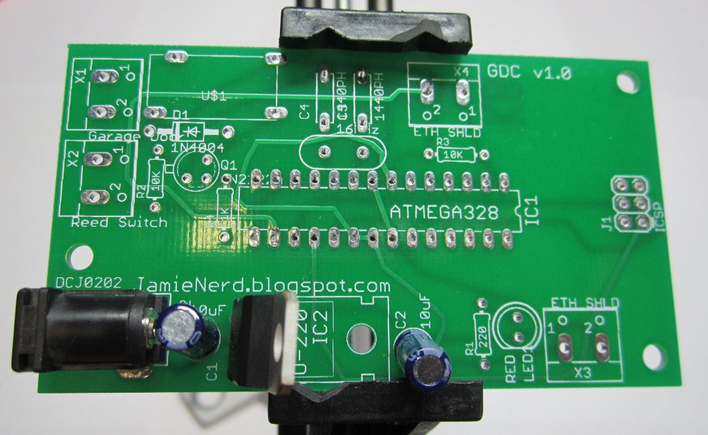
Congratulations! You're done with the soldering, and so your board should look like this:

With this big step out of the way, we can get on to the actual microcontroller. So let's continue to Step 3 - The microcontroller.
Return to previous - Step 1 - parts gathering.
No comments:
Post a Comment