
This section assumes you know the basics of Arduino. If you don't, I referenced a few tutorials/guides in the introduction of this series. But in case you missed them, here they are again:
- Introduction to Arduino (Arduino's website)
- Introduction to Arduino (Instructable...quite long)
- Arduino Tutorial (Ladyada)
- Getting acquainted with Arduino (YouTube video by Jeremy Blum)
First you're going to need the source code (Arduino sketch). You can download it from GitHub here. When you get to my page, click on the 'Download Zip' button:


Copy/extract the 'Ethernet' and 'SPI' folders that are inside the ZIP file, to your 'libraries' subfolder of where your Arduino IDE is installed. For example, my Arduino program lives at:
C:\Program Files (x86)\arduino-0021
So I'm going to copy both of the 'Ethernet' and 'SPI' folders into:
C:\Program Files (x86)\arduino-0021\libraries
Next, copy/extract the actual sketch file (Garage_Door_Controller_Server.pde) into a folder of your choosing. If you have a folder for other sketches, put it in there. If you don't have one, I suggest you make one. Maybe C:\ArduinoSketches, or something similar.
Let's now launch the Arduino IDE, then open the sketch file (Garage_Door_Controller_Server.pde, remember?). If you get a message that looks like this:

Just click on 'OK'. This is just going to create a subfolder with the same name as the file, then move the file into that new subfolder.
Now you should be at the main Arduino screen, with the sketch opened. There are only 5 lines that you should change. I have them marked below:
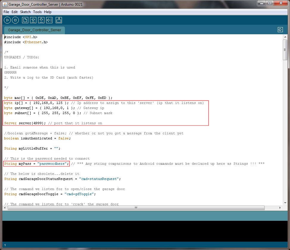
The 5 items you'll probably want to change are:
- ip (the IP address you want this device to have) (please remember this for later in the testing phase - Step 5)
- gateway (IP address of your router)
- subnet (subnet mask of your network, usually 255.255.255.0)
- server (port you want this device to listen in on)
- password (you should definitely change this)
Please write down what you enter for #1, #4, and #5. We're going to need that info later for Step 9 - Smartphone app.
Note that in the sketch that the various IP info use commas (,) instead of periods (.) to separate each octet. You must keep it this way.
Note that in the sketch that the various IP info use commas (,) instead of periods (.) to separate each octet. You must keep it this way.
Please don't change anything below the password. There should be no reason to, unless you really know what you're doing.
Go ahead and save your sketch when you're finished making the changes you need. Then make sure that your Arduino is plugged into your computer, and upload your sketch:
Go ahead and save your sketch when you're finished making the changes you need. Then make sure that your Arduino is plugged into your computer, and upload your sketch:
 |
| 'Upload' button is highlighted above |
After the sketch is uploaded to your chip, then go ahead and move the chip from your Arduino board to your Garage Door Controller board:

I have a chip puller, but I find it easier to use a small flathead screwdriver. Insert it between the actual microcontroller and the holder and twist the screwdriver a little bit. This will make the microcontroller lift up a little bit on one side. Then do the same thing on the other side of the chip:

Go slow and just work each side a little bit at a time, and then you'll have it out in no time:

Before you insert the chip into your Garage Door Controller board, take note of the little notch in the chip at the right end, and note the little notch in the microcontroller holder. These must be on the same side when you put the chip in. If you get it backwards your device won't work. Below is a photo of the chip and GDC board facing the same way:
Now the chip is in the Garage Door Controller board:

Note that when you insert the chip into the holder to be careful making sure that all the pins are going to go in and not bent. Also, once they're all in, you have to firmly push the chip down until it's seated all the way in the holder.
That's it for this part! Next we're going to bring it all together and do a couple basic tests.

I have a chip puller, but I find it easier to use a small flathead screwdriver. Insert it between the actual microcontroller and the holder and twist the screwdriver a little bit. This will make the microcontroller lift up a little bit on one side. Then do the same thing on the other side of the chip:

Go slow and just work each side a little bit at a time, and then you'll have it out in no time:

Before you insert the chip into your Garage Door Controller board, take note of the little notch in the chip at the right end, and note the little notch in the microcontroller holder. These must be on the same side when you put the chip in. If you get it backwards your device won't work. Below is a photo of the chip and GDC board facing the same way:
 |
| Note the notch in the chip and the holder are circled in red |
Now the chip is in the Garage Door Controller board:

Note that when you insert the chip into the holder to be careful making sure that all the pins are going to go in and not bent. Also, once they're all in, you have to firmly push the chip down until it's seated all the way in the holder.
That's it for this part! Next we're going to bring it all together and do a couple basic tests.
No comments:
Post a Comment