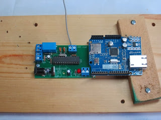
What I used in place of a proper 'project case' is just a couple pieces of wood (a main platform, and a small strip to hold the Ethernet Shield in place):
(Don't worry about all the holes and marks - I'm using a piece of wood that I've used for other things. Additionally, I've already made the holes for everything for this project)
I don't think it really matters what kind of wood, or what the dimensions are, but the thickness matters for the piece that the Ethernet Shield is going to sit on. You'll see why shortly. That little piece to the right that I'm talking about should be about 5/8" thick:
So go ahead and place your board down on whatever you're going to use, but leave plenty of room to the right of it for the Ethernet Shield:
Mark the holes with a pen or something. (The below image shows which holes you need to mark):
Go ahead and remove the board, and drill the appropriate sized holes for the screws you are going to use. Below shows the screws I used:
Screws are installed now:
Now make a couple of holes in the strip of wood (or whatever you are using to hold the Ethernet Shield), and choose your screws to attach this piece to the main platform (in my case, another piece of wood):
I screwed the screws into the wood strip, making them stick out the other side a little bit which makes it a little easier to find the holes in the main platform:
Screwed in:
Now grab your Ethernet Shield and an appropriate-sized screw (to fit the hole that is circled):
Now go ahead and connect your Ethernet Shield to the main circuit board (the 6 male pins on your circuit board should mate nicely with the 6 pin header on the bottom of the Ethernet Shield). Then go ahead and screw that screw in to keep it in place:
The 2 pins on the left end of the Ethernet Shield might get a little too close to the bottom-right mounting screw of your main board, so what I did is bend them away from the screw a little bit (it looks like in the picture that they're actually making contact with each other, but they're not! DO NOT make them them touch each other!:
Let's connect the appropriate wires now. You're going to want to grab/cut 4 wires that are about 5.5"-6" in length. Strip back about 1/4" of insulation at both ends of all 4 wires:
You may need to loosen the screws of the screw terminals a little bit before inserting the following 4 wires. Once you do that we can start with the first wire:
After you inserted the wire, you need to tighten the screw of the screw terminal.
(Please note that it does matter which side of the terminal block you start inserting these wires, so please place the wires in the exact screw terminal and side as I show you.)
Now we'll insert the other end into the Ethernet Shield:
(I know you can't tell from the above picture, but the wire is going into pin #10, which is actually labelled 'ETH CS')
Alrighty, let's insert our 2nd wire:
And connect it to 'RESET' on the Ethernet Shield:
Now insert our red wire into the screw terminal as shown below:
Then connect the other end to '5V' on the Ethernet Shield:
Now connect the last (black) wire to the correct side of the correct screw terminal:
And the other end of the wire goes to one of the 2 'GND' connections on the Ethernet Shield:
Great! This is a good point to test what we've done so far.
Go ahead and connect an ethernet patch cable into the Ethernet Shield and the other end should go to your network hub/switch/router. Then plug in your power supply and you should get some pretty lights:
If you aren't getting any lights (or not all the ones you see from the above photos) check your power and ethernet connections.
If everything looks good, then lets continue to Step 5 - Testing!
Return to previous - Step 3 - the microcontroller.


No comments:
Post a Comment