 |
| My home made circuit board |
This post is an alternate to Garage Door Controller Tutorial - Step 2 - Soldering. The aforementioned post assumes that you bought the professionally made PCB from my store (or downloaded the files on my GitHub and sent them to your own board hours to be fabricated).
However, I'm all about saving money, so wanted to provide you with a way to save yourself a little money (about $9 if you buy from my store, or more $ if you get your own board house to make them for you). So if you made your own circuit board, or want to learn more about doing so, read on...
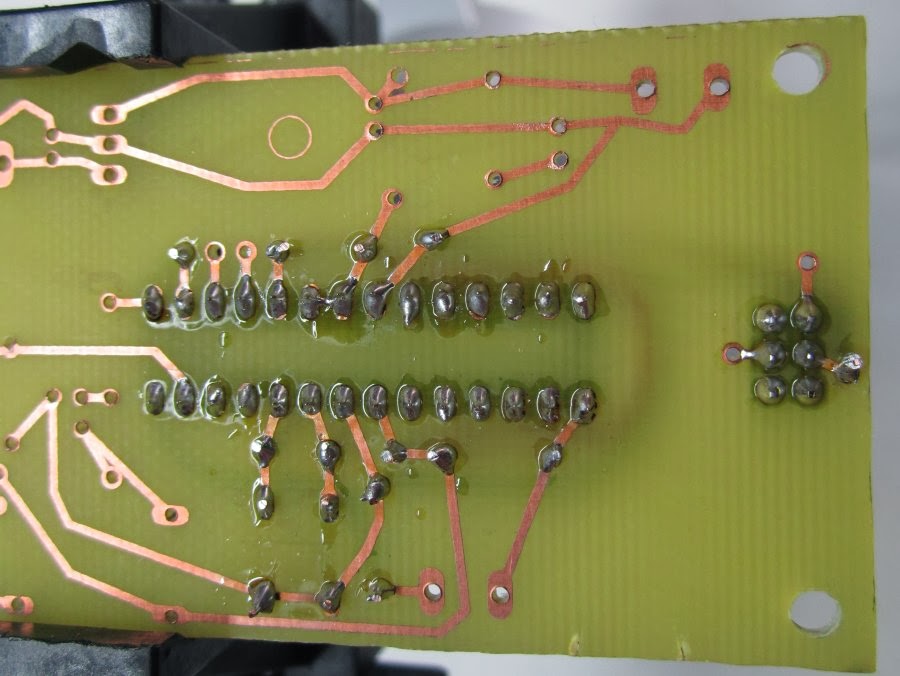
Above is what your homemade board will look like if you choose to make your own. FYI it's not something you can do in 10 minutes though. It does take time and effort. Remember also that after the board is done, you have to drill all the holes. So it's just a question if you want to spend some time doing extra work to save $10. I will also say though that it is a rewarding and fun experience to learn how to make your own PCB and see the finished product.
I'm not going to write a tutorial on how to go about making your own circuit board - there are some pretty good tutorials out there already. Here are some links:
How to make PCBs at home in 1 hour & without special materials
Make Your Own PCBs - Toner Method
Simple DIY PCB Etching
DIY PCB Etching at HubCityLabs
Sponge + Ferric Chloride Method -- Etch PCBs in One Minute
Make Your Own Printed Circuit Boars on a Laserjet! (YouTube video by Make)
Keep in mind that some of these talk about how you have to design a circuit and all of that - you don't have to do that - I've already done the hard work and even provided a ready-to-print PDF for you to download and print:
Here is the direct link to the file hosted on GitHub. I also have this companion pdf which will help you see what component goes where.
Don't forget that you have to drill all the holes for everything before we start soldering. I used 3 different drill bits when doing this:
 |
| #56, #60, #64 (purchased on eBay) |
There are lots of great tutorials on basic soldering, so if you've never soldered, go check some out, then come back here. Here's a few:
Collin's Lab: Soldering - By Collin's Lab / Adafruit Industries
How to Solder Correctly - and Why (Curious Inventor)
Soldering Basics (Sparkfun)
Ok, let's get started!
We're going to start with the 28-pin IC socket. Please note how the notch side is on the right side. With the circuit board laid out the way it is below, make sure that the notch on the IC socket is on the right like the photo:
 |
| With the PCB oriented the way it is above, please make sure that the socket's notch is on the right |
Go ahead and insert the socket into the board. Here's the bottom side of the board after the socket is placed in:

Solder all the pins:
 |
| Hopefully your joints come out better than mine did |
 |
| Front of board after it's soldered |
Now grab the 2 22pf ceramic disc capacitors (C3 and C4) and the 16 MHz crystal (Y1) and insert them into the appropriate holes:

To help keep those from falling out when you turn the board upside down, bend the leads a little bit:
 |
| Bent leads |
Then solder:
 |
| Soldered |
Then clip the leads:


Because I'm not an expert at PCB layout, I couldn't run all my traces on a single side, so we have to solder on some jumper wires. Strip back some wire, insert it into the top hole shown circled below in red:

Then run it between the capacitors and crystal, and around the IC socket. The hole circled in red right below the IC socket is where the other end of this wire is going, so cut it off with a little extra length. I marked mine with a black Sharpie pen where I need to strip the wire. I circled that in blue. Strip that end, and insert into the appropriate hole, flip the board over:

Solder:

Trim the leads:

The green wire is done:
 |
| The wire came out a little bit just before I soldered it. Try to avoid this. |
Next up is the 10K Ohm resistor (R3). Bend the leads at a 90 degree angle like below:

Then insert into the board:
 |
| I apologize about this picture - I know you can't exactly see what holes it's going into |
Flip the board over, pull the resistor all the way through, then bend the leads to help keep it in place:

Solder:

Clip leads:

R3 is now done:

Now let's do our next wire. Strip back some wire, insert it into the top hole shown circled below in red

Then run it around the IC socket. The hole circled in red right below the IC socket is where the other end of this wire is going, so cut it off with a little extra length. I marked mine with a black Sharpie pen where I need to strip the wire. I circled that in blue. Strip that end, and insert into the appropriate hole, flip the board over:

Solder, and trim the leads:

The red wire is done:

Next is our black wire. You probably know the drill by know, so I'm just going to show you the pictures:


Now let's do the 2 sets of headers (J1). Insert both sets with the longest side coming out the top of the board:


It might be a little tricky to get them to stay in place depending on the size of hole you drilled. Since mine weren't staying I used a little bit of Scotch tape to hold them in place while I soldered:

And of course flip your board over and solder them (No need to clip them):

Headers done:

Good. Now let's do our next wire. I'm going to use brown:


Next wire. I used yellow:


Next wire - gray:


Now we're going to do a 10uF electrolytic capacitor (C2). Please note that the white stripe on the capacitor must go toward the inside of the circuit board (facing the IC socket, wires, etc.). The top of the capacitor is circled where the white stripe should be in the below picture:

Here's another angle of C2, with the white stripe circled:

Solder, then clip the leads:

C2 done:

Next up is the 2nd red wire:

Here's a closer view:

And you know the rest:


Next up we have the power jack (J2), 2nd 10uF electrolytic capacitor (C1), voltage regulator (IC2), 220 Ohm resistor (R1), and red LED (LED1). Please note the following: This capacitor has to have it's white strip facing the outside of the board, so it's opposite of the previous one we did. You can kind of make out the top of the stripe on top of the capacitor in the photo below. Also, the LED has to go in a certain way: at the base of the LED, there should be a flat edge which should go toward the outer edge of the board. Another way to make sure you get it correct is that you put the shorter lead of the LED toward the outer edge of the board. I circled (in blue) the 'flat edge' of the base of the LED in the photo below:

And you probably know the rest (no need to snip anything on the power jack):


Now for the 1K Ohm resistor (R4), 10K Ohm resistor (R2), diode (D1), and transistor (Q1). You may recall that resistors don't have polarity so there's no wrong way to put them in. But we have to put in the diode and transistor correctly. Please note that the light-colored stripe (circled in red) on the diode needs to be on the left. And the little tab (circled in blue) on the transistor needs to point to the left :


Lastly, we have the relay (U$1), and the 4 screw terminals (X1, X2, X3, X4). The relay will only fit one way. The screw terminals can be put in 'backwards' however. Make sure you insert them all with the 'metal clips' facing outward - you're going to need to connect wires to these:
All done! We should test the voltage now. Go ahead and plug in the power supply, flip the board upside down, and get out your multimeter. Touch the probes to the 2 solder joints of the voltage regulator as shown below, and your multimeter should show a value very close to 5V (mine is showing 4.98V as you can tell from below):

Congratulations! Now you can continue onto Step 3 - The microcontroller.
No comments:
Post a Comment