Tuesday, December 31, 2013

Garage Door Controller Tutorial - Using the app away from home

As I mentioned in different places throughout my tutorial, you can use your smartphone to check the status of, and open/close your garage door from anywhere in the world. However, as I mentioned in the last post (Step 9) of this tutorial, we set it up so that you can only access your Garage Door Controller from within your own network. This is because it is the easiest way to get you up and running. If you want to expand upon that and be able to access your garage door controller from anywhere, then we need to do a little more work...

Note - You should read this article in its entirety before drawing any conclusions about the path(s) you want/need to take to overcome any problems that you may have.

Please take a moment to look at the following diagram:

No, I do not claim to be an artist

Do you see that vertical red bar that is going through the center of the router? I'm trying to show that the LAN and WAN sides of the router are blocked off from each other. This is actually not entirely true because the router does allow computers from the LAN to access the Internet (WAN), but devices and computers from the Internet (WAN) cannot access the devices and computers inside the LAN. This is by design.

Monday, December 30, 2013

Garage Door Controller Tutorial - Step 9 - Smartphone app


Here we are - this is the last step, and it should be another easy one. You just need to download and install my free Android app now. (The icon for the app looks like the above image)

There are a few ways of doing this:
  1. You can just search for 'Garage door controller' in the Google Play (Google's app store) app. Download/install the app that has the above icon (there may be other garage door controller apps out there)
  2. Go straight to it from your Android smartphone using this Google Play link
  3. Scan the below QR code from your smartphone:


Once you have the app installed, then we just need to configure it, which should only take a few minutes. Go into the 'Settings' screen, by pressing the 'Menu' button on your Android smartphone. You'll see a screen that looks like:


Remember Step 3 - The microcontroller? Back in that step, we entered a few items into the Arduino sketch, then uploaded it to the Arduino. Well now we're going to need a few of those items. Namely, we need:
  1. IP address
  2. Server/port
  3. Password
Now here in the Android app, go through each option and enter the appropriate values (Note - there will probably be 'default' values in each option, so don't worry - just overwrite them). So for 'default IP/domain (url)', enter the IP address that you wrote down in Step 3. Then do the same for 'Default Port' (called 'server' back in Step 3), and then 'Password'.

The last option ('Milliseconds to pause') is a little different. Do you ever 'crack open' your garage door? What I mean is just open it a little bit (just a 'crack') - i.e. when your garage door is closed, you push the garage door opener button, then press it again a second or two right after, which partially opens it. Well that's what this option is for. You specify how many milliseconds between 'button presses'. So the larger the number (fyi: 1000 milliseconds = 1 second), the more the garage door will be 'cracked open'. So if you want a 2.5 second delay, you would enter 2500 milliseconds.

Now we can go back to the main screen, and it should have your information in there now:

Note - your information may be different - the above is just an example

Your IP address will almost surely be different than what you see above. The port will probably be the same though. Notice how it says 'Not Connected/Unknown' in red at the top. And it shows 'Disconnected' for the 'Connection status' below the 'Connect' button. This is because we have to connect to the garage door controller device before we can do anything, so go ahead and click on the 'Connect' button. After you do, you should get a screen that looks like this:

If your screen looks like this, then your garage door is closed

or maybe this:

If your screen looks like this, then your garage door is open

I think the app is pretty straightforward, but just to be thorough, I'll mention a couple of things.

  1. The 'Check here to 'crack' garage door' checkbox is grayed out (not clickable) when the garage door is open. When it's closed, you can check that box and click 'Open Garage Door' and it will 'crack open' your garage door for you.
  2. You need to click the 'Connect' button before you can do anything.
  3. If you did not perform Step 6 - Opened / closed sensor, the status will always show 'open'.
  4. You should click the disconnect button before exiting the app.


I would like to mention that if configuring the app to use the actual IP address of the garage door controller like we did here, you won't be able to connect to it from outside of your network (You won't be able to check the status of, or open/close the garage door outside the physical vicinity of your network). At least, not without some extra work. Please see my post titled 'Garage Door Controller Tutorial - 'Using the app away from home'.

Enjoy!

Return to previous - Step 8 - mount and connect.

Garage Door Controller Tutorial - Step 8 - Mount and connect

We have just a few more things to take care of:
  1. We need to mount your device
  2. Connect it to your actual garage door opener
  3. Connect to the reed (magnet) switch (optional)
  4. Connect your Ethernet
  5. Connect power
Sounds like a lot, but you've already done all the hard work of running wires and cables, so now it's just a matter of hooking everything up. Let's get started!

1. Mount device
I actually have a small area near my garage door opener that allowed me to mount mine on a vertical surface instead of on the ceiling (which should be no problem if you need to do this). Here it is mounted on the small surface:


See the screws at the 4 corners? I just pre-drilled some holes in the wood, then used standard drywall screws to attach it to the drywall, just above my garage door opener.


2. Connect your device to your actual garage door opener
Now we have to connect a couple wires to your actual garage door opener. You know that push button in your garage that you use to open/close your garage door?:


My button looks like the above, but yours will probably look different. The way that your garage door controller works is by simulating a button-push from this button. So what you need to do is hook up 2 wires that are going to connect your garage door opener to your garage door controller device. How do you know which terminals (you probably have 3 of them) on your garage door opener you connect to? An easy way is to just follow the wires from your existing switch to your opener. The back of my opener looks like the following:

Back of my garage door opener
You can see that the existing wire for the existing switch connects to the 2 terminals on the left. So I connected a red wire to the middle terminal, and a black wire to the left-hand terminal. The colors don't actually matter, so don't worry about using different colors or marking them or anything.

Connect the other end of  the wires to the top-left hand terminal block on your garage door controller:


Again, don't worry about which wire is which - it doesn't matter.


3. Connect to the reed (magnet) switch (optional)
If you ran 2 wires for your opened/closed sensor in Step 6, let's connect those now. We're going to connect those 2 wires to the terminal block just below the one we just used:


4. Connect your Ethernet
Let's connect our Ethernet cable to the jack that is on the far bottom right hand of the device:


5. Connect power
Your garage door opener is probably physically near an electrical outlet, so this step should be easy too. Plug in the AC Adapter into the outlet, and into your device, and your done with the hardware!

See the power cable plugged into the power jack at the bottom left of your device? Well plug it in!
I highly recommend that you use a surge protector instead of plugging directly into the outlet.

The power LED should come on and you'll start to see some lights flashing on the Ethernet Shield. Pat yourself on the back and rejoice - you are done! (With the hardware aspect anyway)

Well, hardware is no good without software, right? Right. That brings us to the last step - Step 9 - Smartphone app. (Don't worry, this is easy)

Return to previous - Step 7 - your network.

Garage Door Controller Tutorial - Step 7 - Your network

Your device is pretty much useless without being on your network. You have at least 3 options to get it on the network. The idea is that you need to connect a networking/patch cable from your device to your network.

Option 1 - If your garage door controller is going to be close enough to your router/switch, you can just use a pre-fabbed Cat5/Cat5e/Cat6 patch cable from the router/switch to your garage door controller.

I don't think this one really needs much explanation. Just tack up your patch cable from the garage door controller to your router/switch, plug it into your router/switch, and call it a day.


Option 2 - Very similar to option 1, except that this way is theoretically cheaper, but requires a little more work.

If you need to run the network cable a longer distance than a patch cable that you can get a hold of, or if you already have some, you can run un-terminated Cat5/Cat5e/Cat6 network cable (cheaper than pre-fabbed patch cables). Then put the end connectors (RJ45s) on the ends yourself.

This is the route I took for my own house...here's a couple photos:

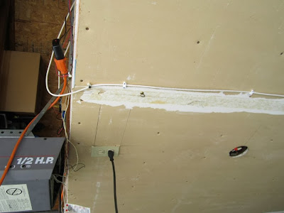
White Ethernet cable tacked to the ceiling of my garage

The other end connected to my network:

Yes, it's a little messy


It's actually not difficult to put the end connectors (RJ45s) on yourself. This Instructable is pretty good and easy to follow. Or, if you prefer a video, this is a pretty good brief tutorial.


Option 3 - If running cable is going to be too difficult/inconvenient, and you have a wireless network already, you can use something like a TP-Link TL-WR702N Wirelss N150 Travel router. You configure it for your network as a 'client' instead of a 'router', then plug a short, inexpensive patch cable from it to your garage door controller, and you're all set.

Just to elaborate on this option a little bit:
If you do want to use a wireless device such as the above, there is a little configuring you need to do. You'll need some information about your wireless network, such as: SSID, MAC address of your existing router/access point, WEP Key Index (if using WEP), and the key/passphrase/password.

As far as how everything fits together physically, here's a photo of a finished installation that I did for one of my sisters:


The TP-LINK device is the blue square device near the top-right of the image above. It has an Ethernet patch cable coming out the bottom (it's the dark gray cable coming out the bottom-left of the device) connecting to the garage door controller. The lighter colored cable coming out the bottom to the right of that is the power cable. So adding this extra little device is actually pretty simple and straight-forward.

Now that that's done, let's go to Step 8 - Mount and connect.

Return to previous - Step 6 - opened/closed sensor (optional).

Garage Door Controller Tutorial - Step 6 - Opened / Closed sensor (optional)

This step is optional, but I highly recommend it. It allows you to know if your garage door is opened or closed. This in itself may be a highly valuable feature - do you ever get the feeling that you forgot to close the garage door when you left your house? Yeah, well, then you want to do this step.

First you need to decide where you're going to install your device, and where you're going to install your reed switch (this will probably be a stationary part of your garage door track or something that will be physically close to your actual garage door). Once you decide this, run your 2 wires from one area to the next, leaving some extra slack (I like to give myself an extra foot or 2). You should 'tack' them to the walls (using the appropriate staples, or wire-ties and screws, or whatever else you like to use), or whatever other surface they're against, so that they stay in place, and are clean-looking.

After the wires are ran, you'll need some way of physically attaching the reed switch and magnet. Here's what I used:

Bracket for the magnet on the left, reed switch in the center, bracket for reed switch on the right


Garage Door Controller Tutorial - Step 5 - Testing

We need to make sure that everything is working before we continue. Remember that IP address that I asked you to remember in Step 3? Well we're going to need that now.

On a computer that is connected to the same network as your garage door controller, get to a command prompt. There are a couple easy ways of doing this:

Method #1 - On your keyboard, press the Windows key and 'r' at the same time. In the window that appears, type in 'cmd' (without the apostrophes), then hit 'Enter' on your keyboard.

Method #2 - Click on your 'Start' button, click 'Programs' (or 'All Programs'), 'Accessories', then 'Command Prompt'.

Whichever method you choose, you'll end up with a black window.Welcome to the 'Command Prompt'. It should look something like this:


Garage Door Controller Tutorial - Step 4 - Putting it together

Now that your Garage Door Controller is all soldered together, and your programmed chip is installed, it's time to combine the main board and the Ethernet Shield.

What I used in place of a proper 'project case' is just a couple pieces of wood (a main platform, and a small strip to hold the Ethernet Shield in place):
(Don't worry about all the holes and marks - I'm using a piece of wood that I've used for other things. Additionally, I've already made the holes for everything for this project)


I don't think it really matters what kind of wood, or what the dimensions are, but the thickness matters for the piece that the Ethernet Shield is going to sit on. You'll see why shortly. That little piece to the right that I'm talking about should be about 5/8" thick:


So go ahead and place your board down on whatever you're going to use, but leave plenty of room to the right of it for the Ethernet Shield:


Garage Door Controller Tutorial - Step 3 - The microcontroller


This section assumes you know the basics of Arduino. If you don't, I referenced a few tutorials/guides in the introduction of this series. But in case you missed them, here they are again:


First you're going to need the source code (Arduino sketch). You can download it from GitHub here. When you get to my page, click on the 'Download Zip' button:


Garage Door Controller Tutorial - Step 2 - Soldering

Now we get to start the fun part - soldering!

Note that this step is assuming you're using the professional PCB that you purchased from my store. If you want to make your own PCB at home, I have the files @GitHub for a single-sided home-made board available if you want to make your own board. And a separate tutorial for soldering on it.

There are lots of great tutorials on basic soldering, so if you've never soldered, go check some out, then come back here. Here are a few:
Collin's Lab: Soldering - By Collin's Lab / Adafruit Industries
How to Solder Correctly - and Why (Curious Inventor)
Soldering Basics (Sparkfun)


Ready? Ok, here we go...

Garage Door Controller Tutorial - Step 1 - Parts Gathering

Here are the parts:


BOM (Bill of Materials) in relation to above image:

A.N/A9V Switching power supplyPart# TOL-00298 @ Sparkfun.com1$5.95$5.95
B.N/AArduino Ethernet ShieldPart# 83-13141 @ MCMElectronics.com1$34.99$34.99
C.R2,R31/4W 10K resistorPart# CF14JT10K0CT @ Digikey.com2$.08$.16
D.R11/4W 220 OHM resistorPart# S220QCT @ Digikey.com1$.08$.08
E.R41/4W 1K resistorPart# CF14JT1K00CT @ Digikey.com1$.08$.08
F.IC128 pin IC SocketPart# 3M5480 @ Digikey.com1$.70$.70
G.IC1ATMega328 w/Arduino BootloaderPart# DEV-09217 @ Sparkfun.com1$5.50$5.50
H.U15VDC RelayPart# PB874 @ Digikey1$1.61$1.61
I.D1General Purpose 1N4004 DiodePart# 1N4004FSCT @ Digikey.com1$.18$.18
J.Y1Crystal 16MHzPart# X1103 @ Digikey.com1$.81$.81
K.C3,C422 pF Ceramic Disc CapacitorPart# 399-4344 @ Digikey.com2$.44$.88
L.C1,C210uF Electrolytic CapacitorPart# P5161 @ Digikey.com2$.20$.40
M.Q12N2222A TransistorPart# 497-3108-5 @ Digikey.com1$2.76$2.76
N.J2Power Jack 2.1mm x 5.5mmPart# CP-102A @ Digikey.com1$.92$.92
O.IC2Voltage Regulator 5VPart# 497-1443-5 @ Digikey.com1$.55$.55
P.LED1Basic LED (Red)Part# COM-00533 @ Sparkfun.com1$.35$.35
Q.X1-X4Screw Terminals (2 pos.)Part# ED2580 @ Digikey.com4$.42$1.68
R.J1Male breakaway headersPart# PRT-00116 @ Sparkfun.com1$1.50$1.50
S.N/AMagnet Cube (1/4")Part# COM-08643 @ Sparkfun.com1$1.50$1.50
T.N/AReed SwitchPart# COM-10601 @ Sparkfun.com1$1.95$1.95
U.N/APCBPart# GDC10PCB @ jamienerd.blogspot.com1$5$5

Total (before tax, S&H, etc.): $67.55

Prices tend to fluctuate a little bit, so don't be surprised if by the time you click those links, the prices aren't the exact same. (They may be a little higher or lower)

Technically, you will need a few extra things (you may already have some on hand), such as:

Wire (to run a couple of wires from your garage door controller to your actual garage door opener)
Electrical tape
Krazy Glue
Brackets and screws (to mount to your garage door for the reed switch and magnet)
Some Cat5/5e/6 network cable

And of course there are a few basic tools you're going to need:
Knife (or wire stripping/cutting tool)
Soldering iron
Solder
Small screwdriver

The 2 lists above are only a couple of general lists - what you will really need depends on the way you go about your project - you may need more or less tools/supplies.

You'll also need a way to program your microcontroller - an actual Arduino board would be an easy way.

If you want to save a little money, you could skip the screw terminals (Q). This would mean though that you would have to solder wires onto the PCB instead of having the convenience of having 'removable' wires. You could also technically skip the magnet cube (S), and reed switch (T) which is the 'sensor' that can tell you if your garage door is open or not. If you decide to skip those, the Android app would always show your garage door as 'open'. You should probably only skip this if you have another way of knowing the status of your garage door (camera, etc.).

I know this isn't the cheapest project, but to me, it's worth the awesomeness of being able to open/close your garage door with your Android cell phone/tablet! If you want some tips on how you can save yourself a little money, please check out my FAQ, under the 'Is there anything I can do to bring the total cost of the project down?' question

On the other hand, if you want to spend a little less time (but a bit more money), I have a few options in my store, including full assembled board, or a full kit, etc.

Once you have all your parts, let's continue to Step 2 - Soldering.

Return to previous - introduction.

Garage Door Controller Tutorial - Introduction


I call this project 'Garage Door Controller'. The hardware is based on Arduino, and the 'software client' is an Android app. I do not have any immediate plans to release an iOS version of the software as I have no interest in developing on that platform (I'm not a fan of Apple's closed source model). However, if there is someone out there interested in porting the program to iOS, you may contact me and we can discuss that.

With the hardware and the free Android app, you will be able to see if your garage door is opened or closed, and you will actually be able to open and close it...from anywhere in the world you have Internet access.

Before you go any further, let me just make a couple things clear:
  1. You need to have a working automatic garage door opener
  2. I'm assuming you have the ability to run an Ethernet cable from your network switch/router to your garage door controller device, which should be near the general vicinity of your automatic garage door opener. (Technically you don't have to run an Ethernet cable to your router/switch...if you have a wireless router and/or Access Point, you could use one of these. I explain this more in Step 6.)
  3. I'm assuming you have the ability to run (2) lengths of wire (light gauge/low voltage) from your garage door controller device to the vicinity of your garage door. This is your 'sensor' that will tell you if your garage door is open or not. (This is not required, but recommended)
  4. I'm assuming you have a way of programming an ATMega328 microcontroller. For example, you have a computer running Windows/Mac/Linux (to run the free Arduino IDE), a standard USB cable, and an Arduino board (or similar/compatible). If you are brand new to Arduino, you should check out some of the following links:

All the source code for the Arduino and the Android app are linked below. The Android app is called 'Garage Door Controller' and is available for free on Google Play.

There is a possibility that you may run into a slight inconvenience when using this system if your router does not support loopback. Please check out my post, Garage Door Controller Tutorial - Using the app away from home for more info on this.

The project cost can vary wildly, so a very rough estimate would be around $40 - $85. It depends on several factors. Please see my FAQs page under the question, 'Is there anything I can do to bring the total cost of the project down?'. Obviously the more components you already have on hand, the cheaper it will be (it may actually only cost you a few dollars!).

How does this device work? You connect your garage door controller to the Internet by connecting it to your network. Connect the garage door controller to your automatic garage door opener. Install a reed switch and magnet on your actual garage door, and the (2) wires that come off of that connect to your garage door controller. Download and install my free Android app to connect to the garage door controller over your network and/or over the Internet to check the status of the door, and open and close it.

Here is a video of my device in action:


Downloads/links for this project (all on GitHub):
  1. The Arduino sketch (and supporting files)
  2. Android app source code
  3. Circuit board files (for submitting to professional board house)
  4. Circuit board files (for making your own circuit board at home)

I tried to break this project down into several smaller steps:
  1. Step 1 - Parts Gathering
  2. Step 2 - Soldering
  3. Step 3 - The microcontroller
  4. Step 4 - Putting it together
  5. Step 5 - Testing
  6. Step 6 - Opened / Closed sensor (optional)
  7. Step 7 - Your network
  8. Step 8 - Mount and connect
  9. Step 9 - Smartphone app
  10. Using the app away from home (supplemental/optional)


In the next step, I provide direct links (to Digikey, Sparkfun, etc.) to the individual parts you'll need. As an alternative, you can check out my store which includes the full kit, fully assembled device, etc which may be more convenient for you.

Ready? Let's go - Step 1 - Parts Gathering!


Disclaimers:
1. I am not responsible for any damage/harm you may do to your garage door, your phone, yourself, or anything/anyone else during this project.
2. I am not a professional electronics engineer, or a professional programmer. I have had no prior Android development experience, so I picked up a couple of books and started learning for this project. In other words, please don't laugh at my code. On the other side of the coin, I would love to hear ideas/suggestions from the more experienced programmers out there.
3. Even though I've implemented a 'password' requirement for the Android to be able to send commands to the Arduino to open the garage door, it's not very strong security. It's sent as plain text over the internet, so anyone with the right software and know-how could intercept it, and start opening/closing your garage door with just a little more info. I do have some ideas about implementing better security, so in future Android/Arduino releases I may implement something...but can't make any promises.